Assembly Tutorial
Welcome to the LAFVIN Retro Game Kit assembly tutorial! This guide provides two assembly methods - choose based on your needs and experience level.
Assembly Overview
The LAFVIN Retro Game Kit offers two assembly methods:
Method 1: Quick Assembly Mode (Recommended for Beginners) → Jump to
Uses LAFVIN Retro Game Hub expansion board
Plug-and-play modules, no wiring required
Assembly time: approximately 15-20 minutes
Ideal for quick start and immediate gaming
Method 2: Breadboard Mode (Advanced Users) → Jump to
Uses standard breadboard with flexible layout
Fully customizable hardware connections
Assembly time: approximately 40-60 minutes
Ideal for learning hardware principles, debugging, and modifications
Comparison |
Quick Assembly Mode |
Breadboard Mode |
|---|---|---|
Difficulty |
⭐⭐ Simple |
⭐⭐⭐⭐ Advanced |
Assembly Time |
10-15 minutes |
40-60 minutes |
Wiring Amount |
Minimal (uses expansion board) |
Extensive (fully manual wiring) |
Flexibility |
Fixed layout |
Fully customizable |
Target Users |
Quick experience |
Hardware learning |
Debugging Difficulty |
Low |
Medium |
Modification Space |
Limited |
Flexible |
We recommend using the first assembly method for quick hardware verification and software familiarization
Warning
Important Notice:
Regardless of which assembly method you choose, please note:
Ensure all modules are powered off during assembly
Do not plug or unplug modules while powered on - this may cause hardware damage
Carefully verify pin connections to avoid incorrect wiring that could damage components
Required Tools
Recommended: Tweezers (for organizing jumper wires)
Good lighting environment
Flat work surface
Component Checklist
Before starting assembly, please confirm you have received all components. For detailed list, refer to Component List.
Method 1: Quick Assembly Mode
This method uses the LAFVIN Retro Game expansion board. Most connections are already completed on the board - you simply need to insert the modules.
Step 1: Prepare the Expansion Board
1.1 Inspect the Expansion Board
Take out the LAFVIN Retro Game expansion board and check:
Board surface is undamaged
All sockets are intact
Pin labels are clearly visible
Step 2: Install Core Modules
2.1 Install TFT Display
Installation Steps: 1. First, secure the copper pillar to the base plate using the nut. 2. 2. Install the TFT screen onto the base plate as shown in the diagram (pay attention to the female connector and orientation). 3. 3. Tighten the screws using a Phillips screwdriver.
2.2 Install TFCard Module
Installation Steps:
Locate the socket labeled “TFCard Module” on the expansion board
Align the TFCard module’s pin headers with the socket
Ensure the TF card slot faces outward for easy card insertion/removal
Gently press down to ensure pins are fully inserted
2.3 Install Amplifier Module
Installation Steps:
Locate the socket labeled “Amplifier Module” on the expansion board
Align the amplifier module’s pin headers with the socket
Ensure the audio output interface faces outward
Gently press down to ensure pins are fully inserted, then connect the speaker to the amplifier module
Finally, install the speaker onto the back using adhesive dispensing.
2.4 Install ESP32S3 Controller Module
The ESP32S3N16R8 is the core controller of the entire gaming console.
Installation Steps:
Install the ESP32S3 module into the socket on the back of the board
Confirm module orientation: antenna direction should match the board silkscreen
Align the ESP32S3 module with the socket and gently press down
Ensure all pins are fully inserted and the module fits tightly against the board
Warning
Do not apply excessive force during installation to avoid damaging pins. If pins cannot be inserted smoothly, check if they are properly aligned.
Method 2: Breadboard Mode
This method uses a standard breadboard and requires manual completion of all wiring. Suitable for advanced users who want to deeply understand hardware connection principles.
Step 1: Breadboard Preparation
1.1 Connect Two Breadboards
You can refer to our installation diagram or design your own layout. The connection diagram and IO-module reference table are as follows:
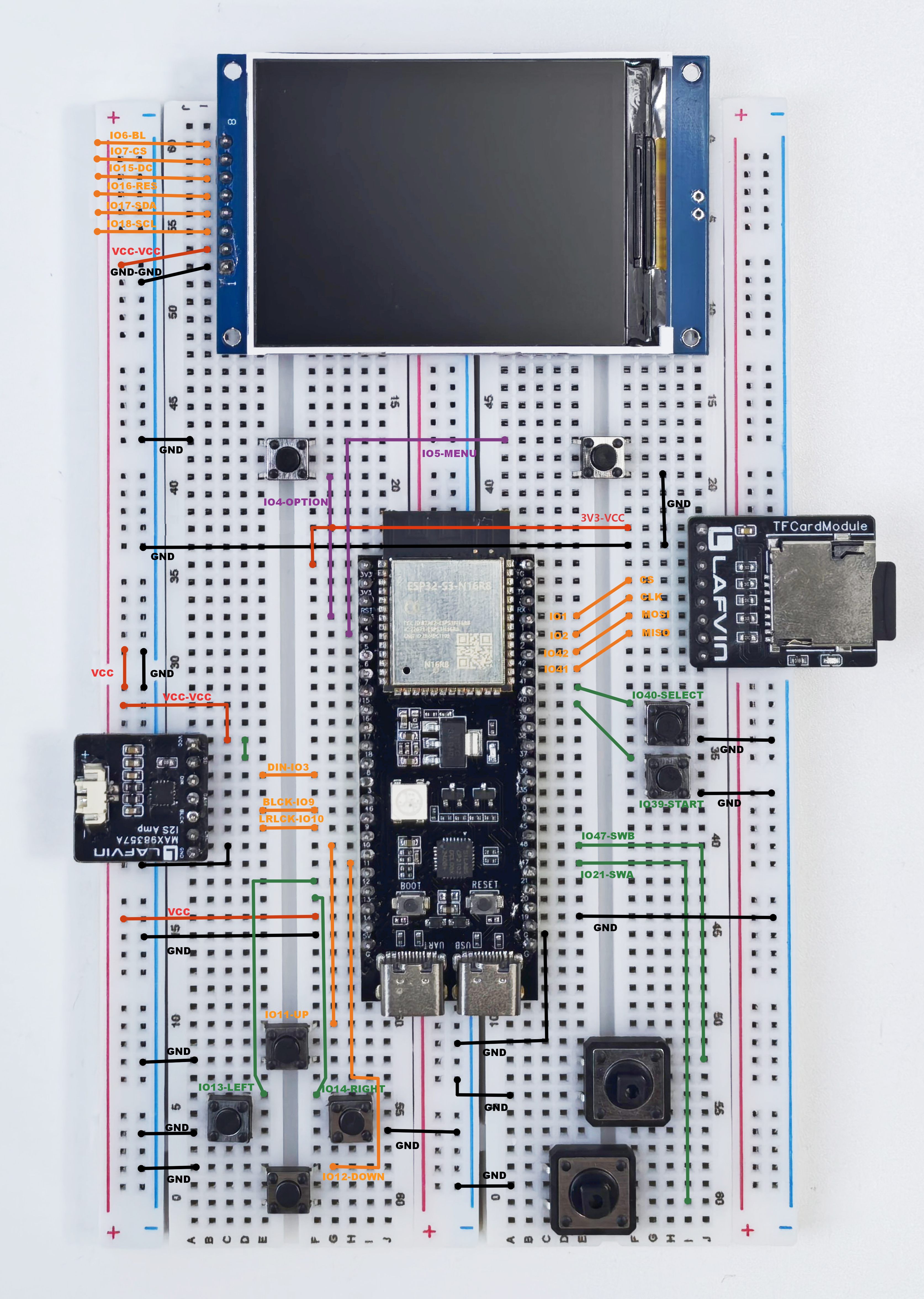
TFT Display Pin Connections
TFT Pin |
ESP32S3 Pin |
Description |
|---|---|---|
BL |
GPIO 6 |
Backlight control |
CS |
GPIO 7 |
Chip select signal |
DC |
GPIO 15 |
Data/command select |
RES |
GPIO 16 |
Reset signal |
SDA |
GPIO 17 |
SPI data output |
SCL |
GPIO 18 |
SPI clock |
VCC |
5V |
Power supply |
GND |
GND |
Ground |
TFCard Module Pin Connections
TFCard Pin |
ESP32S3 Pin |
Description |
|---|---|---|
VCC |
3V3 |
Power supply |
GND |
GND |
Ground |
DO2 |
NC |
(Not connected) |
CS |
GPIO 1 |
Chip select signal |
CLK |
GPIO 2 |
SPI clock |
MOSI |
GPIO 42 |
SPI data output |
MISO |
GPIO 41 |
SPI data input |
DO1 |
NC |
(Not connected) |
Amplifier Module Pin Connections
Amplifier Pin |
ESP32S3 Pin |
Description |
|---|---|---|
VCC |
5V |
Power supply (Note: 5V!) |
GND |
GND |
Ground |
SD |
VCC (shorted to amplifier VCC) |
Amplifier enable (shutdown control) |
DIN |
GPIO 8 |
I2S data input |
GAIN |
NC |
Gain control (not connected) |
BCLK |
GPIO 9 |
I2S bit clock |
LRCLK |
GPIO 10 |
I2S left/right channel clock |
Button Pin Connections
Button |
ESP32S3 Pin |
Description |
|---|---|---|
D-pad - Up |
GPIO 11 |
Direction control - Up |
D-pad - Down |
GPIO 12 |
Direction control - Down |
D-pad - Left |
GPIO 13 |
Direction control - Left |
D-pad - Right |
GPIO 14 |
Direction control - Right |
A Button |
GPIO 21 |
Game button A (Confirm/Jump) |
B Button |
GPIO 47 |
Game button B (Cancel/Attack) |
Start Button |
GPIO 39 |
Start/Pause game |
Select Button |
GPIO 40 |
Select function |
Menu Button |
GPIO 5 |
Open system menu |
Option Button |
GPIO 4 |
Option settings |
Each button has one end connected to the corresponding GPIO pin and the other end connected to GND (ground). The ESP32S3 will enable internal pull-up resistors, and the pin level becomes low when the button is pressed.
Warning
Power connections are critical! Incorrect power and ground connections may cause short circuits and hardware damage
Tip
Wiring Tips:
Connect one module at a time, complete it before moving to the next
Use different colored jumper wires to distinguish different functions
Take photos of the wiring process for later reference
Use tweezers to adjust jumper wire positions
Breadboard Mode Assembly Complete
Congratulations! You have completed the breadboard mode assembly. Although this method is more complex, it gives you complete mastery of hardware connection principles.
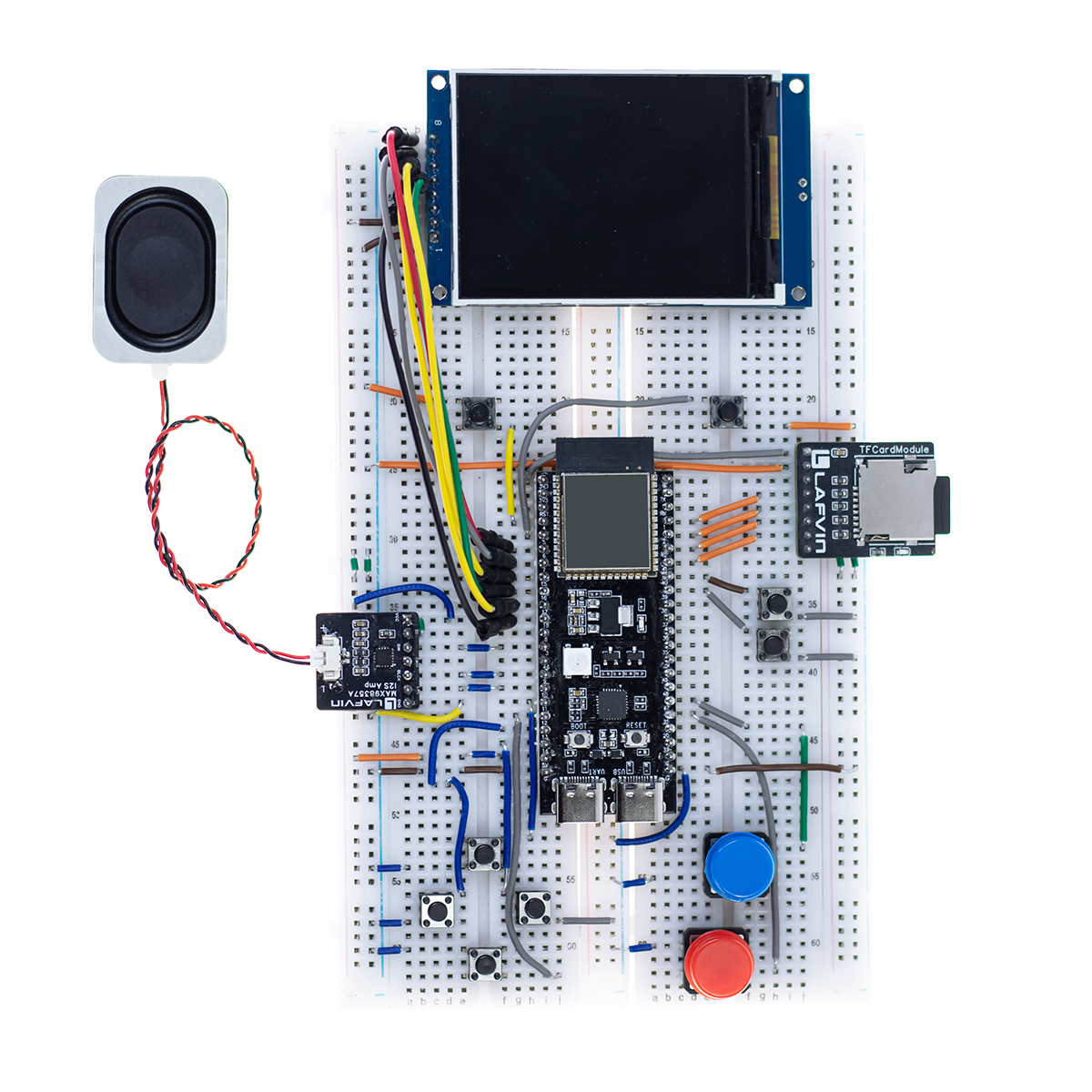
Final Verification Before Power-On (Applies to Both Methods)
Danger
Before powering on for the first time, please complete the following final checks:
✓ Power connections are correct
✓ No short circuits (power and ground lines not touching)
✓ All modules are securely installed
✓ Pin connections verified against tables
✓ TFT display cable connections are correct
If you have any doubts, do not power on! Check connections first!
Assembly Complete
Regardless of which assembly method you chose, the hardware portion is now complete.
Next Steps
After hardware assembly is complete, you need to:
TF Card Preparation - Prepare and format the TF card
Firmware Flashing - Flash firmware to ESP32S3
Usage Guide - Learn how to use the gaming console
If you encounter problems during assembly, please refer to Troubleshooting.
Having Issues?
If you encounter difficulties during assembly, please check Assembly Issues for detailed troubleshooting guides.
You can also:
Visit the LAFVIN official website for more resources
Contact the technical support team
Wishing you smooth assembly and happy gaming!